RIGGING AND CREATURE FX
WEEK 1
Rigging overview- Tentacle
In the first week of rigging and creature FX, we got introduced to the rigging basics by creating a rigged tentacle. We used mash to multiply the tentacle and we attached them to a sphere. Then, we used mash again to multiply the sphere and the tentacles, and we added camera, light, textures and aiAtmosphere.
First, we created a tentacle by using soft selection tool on a cube.
Then, we went to Skeleton and 'Create Joint' tool, and added 4 joints with 3 vertices of spacing between each.
We created controllers for joints, by adding 3 NURBS circles.
We created an animation by using the expression editor with different expressions on different axis.
I played around with mash nodes such as Time, Random or Signal to make the animation more interesting.
Below are some screenshots showing my process as well as a playblast render.


Here is my playblast render. I have also added textures and lights to the scene but because the Arnold render and Arnold playblast takes a lot of time on my laptop, I only did a playblast and one frame with arnold render.

WEEK 2
Joint Creation
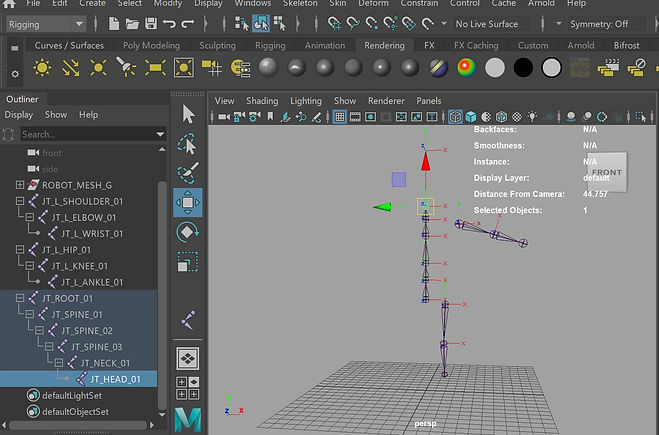
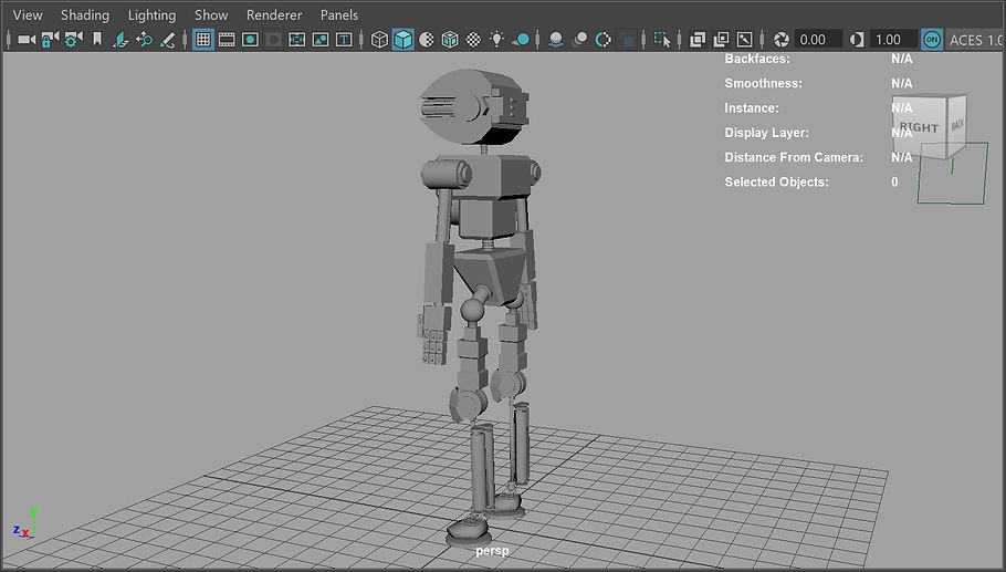
This week we learnt about joints, how to create them and how to use them. We experimented on a simple robot.
I created joints for the arms, legs, head, body.
I then started to mirror the joints to the other side by using the mirror joint tool for arms and legs to create a full skeloton.
Notes:
-to snap joints to X axis (to grid): hold X when creating them

After creating the joints, it's time for parenting.
We use parent constrain to make 2 objects behave as a parent-child relationship, so the position of an object depends of the other object.
I used parenting by selecting the relevant joints and objects and pressing P on the keyboard.


WEEK 3
Skinning
This week we played around with a 3D arm model. We rigged it and then we looked at paint skin weights tool. This tool allows us to paint weight intensity values on smooth skin.
I start by creating joints for the arm and naming them.

Then, I do the fingers
Note: to expand a selection ->CTRL+right click->grow selection->grow

I connect the joints by selecting the finger first, then the arm and clicking on P.
I select the root joint and the arm and Skin->Bind Skin, then I make a simple animation
Paint Skin Weight Tool
->select the mash ->right click->paint skin weight tool
I start with root: Paint operation: replace ->value:1000 ->flood
Then, I move to shoulder. First, I need to lock everything besides root and shoulder
I select the shoulder vertexes ->paint mode -> replace ->value:1000->flood
I expand the selection and paint mode -> smooth->flood


Select the joint and then the mesh -> skin-> Bind Skin
Paint Skin Weights Tool
Spot light at the origin
Arm -> Arnold-> Standard Surface -> \
light -> Arnold -> Exposure up around 10.000
Spot light attributes -> cone and penumbra
Render settings ->Arnold render-> environment ->atmosphere ->create aiatmposphere volume
Density up
Color
Toon Rendering
Material ->aiToon (Arnold)
lights->skydome
camera->0
exposure _>down around -3.000
Render settings->Arnold settings->filter->type contour
Mesh->aitoon ->edge->color, width scaling
sphere under the mesh -> the previous material ->edge detection->id difference
Base->color
Base->tone map ->ramp->
Select color
Type Vramp; interpolation -> none
duplicate spotlight ->exposure -1000
mesh->aitoon-> stylized highlight

WEEK 4
Rigging Controls Robot
This week we looked at another robot rig to explore more the rigging controls in Maya. We created rigging controls for the robot MKII.
We used nurbscircles (controls for joints) and snaped them to joints. To do this, we selected first the control and then the joint, we parent it and zero out the translate values from the channel box.
Shift+P to unparent -> adjust the rotation
Modify->Freeze transformation
Next step was to constrain the rotation of the joint to the control:
->select the control then what we want to be constrained
->constrain->orient

When we finish with the arm controls, we need to parent them right

Arm IK Control
Skeleton->Create IK Handle
We select the beginning and the end of a joint
Elbow Pole Vector
We place a control behind the elbow, select the control then the ik handle -> constrain->pole vector
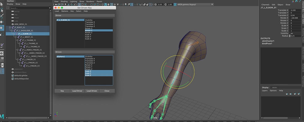
Using Set Driven key for claw controls
We click on load driver with claw control selected.
Driven will be represented by claw parts.
Then, we select all 3 rotation controls and click on key for each claw
At another frame we change the claw open from 0 to 1, we open the claws and select key again
Claw control rotation expression
We add another attribute for claw control:wrist spin
With claw selected,
R click on wrist spin ->create new expression and we write the expression

WEEK 5
Rigging Controls Robot 2
This week we used the robot MKII file like seen in the previous week but this time we created rigging controls for its spine. Also, we created some controls for the eyes. In the second half of the lesson, we created an emoji smiley face using MASH.
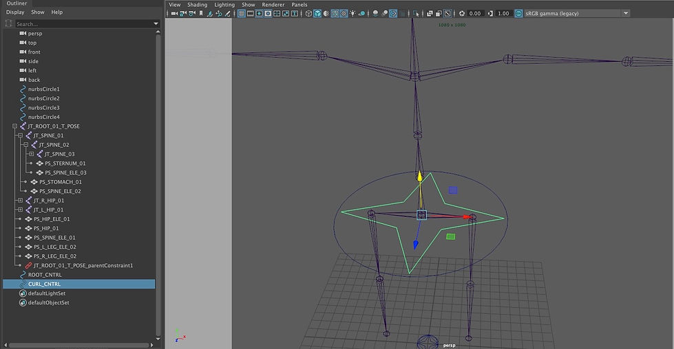
Rigging Controls For Spine
I used a nurbsCircle that I parented to the hips of the robot and then, I added a master controller in order to move the entire robot.
Set driven keys
For this, we had to add 2 new attributes: one for the froward and backward bending and another one for bending right and left. I used a float data type and wrote in a minimum of -1 and a maximum of 1. The numbers represent how the spine will act in whether it is curling forwards or backwards.
Then, I used the set driven for spine joints that I wanted to animate.The driver is the root control and the driven is represented by spine 1,2,3. First, it will only affect the rotate Y (curling forward)
I then repeated the process, but I changed the rotate Y to the rotate Z (curling backwards)
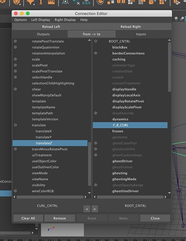
Finally, I created a controller for the curling of the spine and on connection editor tab, I made sure it was hooked up to the attributes that I created.
Screenshots and recordings of my progres:
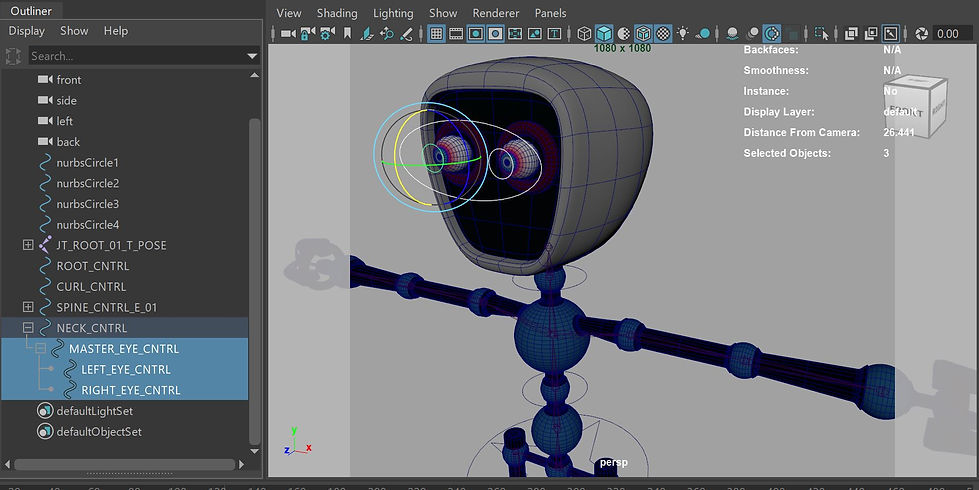
Rigging controls for eyes
I created 3 controllers, one for each eye and then a master controller that will move both of them. I parented the controllers over each eye. I used aim constraint in order to make the eyes move with the controller
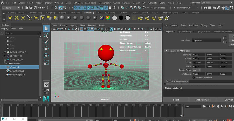
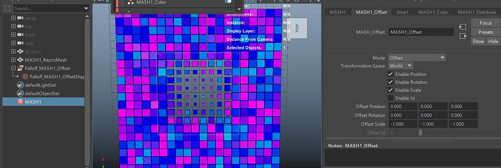
Mash Smiley Face
I imported a Cube and a Sphere and I created 'Mesh'. I set the Sphere mesh into 'Input Mesh' section on Mesh Distribute node. Then, I added 'Offset', 'Random' and 'Signal' Nodes.

I added 2 colour nodes: black and pink and I placed 2 spheres ansd a cube for the eyes and mouth.
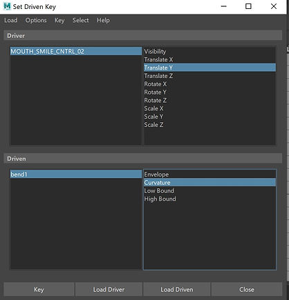
For mouth, I used Deform->Bend. Then, I used FallOff, I made a connection and I shaped in the face_mash. FallOff Object controls a falloff volume using an input object for its shape.
Then, I created 2 controls to animate the smiley face and I set Driven Keys.
Arnold Render
In order to render in Arnold and render the colors, we need to turn on mash's vertex color. I imported aiUserDataColor and connected to Base Color to get the vertex color information into the color channel of the mash's shade.

Assignment 1
For this first assignment, I modeled and rigged a mechanical machine using Maya. The rig needed to be presented in the form of a Rig Demo, which should include different aspects of the rig.
I created a simple robot. First, I made sure that I modeled it along with the origin point. This way, the model is symetrical and I could also mirror different parts such as legs and arms.
I then added some lighting. I added a skydome light and I used a hdri image, for which I turned down the visibility of the camera and 2 area lights. I also textured the robot in Substance Painter.


Then, I used substance painter to texture it.

Back in Maya, I continued with the joints.I used the joint creation tool and I created joints in the center of specific parts of the body like arms, legs, neck, etc. After making the joints, I made sure that where I rotated the joints when making them, I write the joints transform attributes(rotation) into joint orient, and then I zero out the transform attributes. I used mirroring for the arm and leg joint.
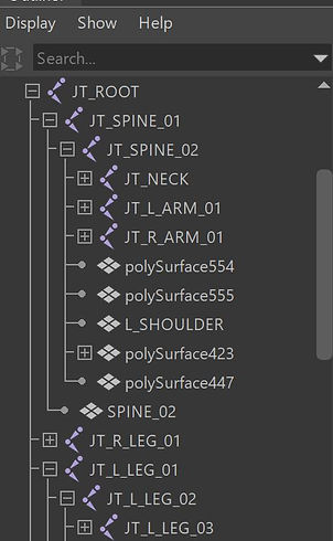
Then, I set up the hierarchy and made sure that the joints are correctly parented to one another.
Note: the joint after the neck is only made to keep the arms in place, is not made to be rotated when animating

Setting FK Controls.
In order to move the arms easier, I made some FK Controls by using nurbs circles that I moved in the centre of the joints, freeze the transformation and then I used orient constraint on the controls, so the arms can only rotate.
Then, I added more FK controls for the neck, chest, root, etc.
I also made iKHandles for the legs. I came into some difficulties as after I selected the joints and created the IKHandle, the IKHandle was placing in the wrong way and the leg was not bending right. However, I found a solution on the internet. I set a preferred angle. Rigging menu→ Skeleton →Set Preferred Angle.
First, I rotated the bend joint in the direction I wanted it to bend. I selected the joint where the IK handle begins(start joint), and clicked the “set preferred angle” tool. Finally, I restored rotation on the bend joint back to what it was before I modified it. Then, when I created the IK handle again, the joint will bend in the directionI just set it to.


Then, I created some attributes and expressions!
First, I added an attribute which I called head spin and makes the robot head spin. I set the attribute to a float data type and for the expression I used the code below:
float $neckRot = NECK_CNTRL.NECK_SPIN;
if ($neckRot == 0) {
head.rotateY = 0;
} else
{
head.rotateY = frame*$neckRot;
}
I have also added a similar attribute called hand spin, which makes the hands spin.
float $wristRot = L_WRIST_CNTRL_01.WRIST_SPIN;
if ($wristRot == 0) {
L_WRIST_CNTRL_01.rotateY = 0;
} else
{
L_WRIST_CNTRL_01.rotateY = frame*$wristRot;
}
I set driven keys for spine_01 control. I added 2 attributes: left&right curl and forward&backward curl. So then, when I change the values of one of these attributes the robot moves accordingly.
Then, I created a simple animation to demonstrate what my rig is capable of:
WEEK 6
This week was about creating simple hydraulics in Maya. We learned about creating psitons, springs and hydraulics for robot's arm.
For the first exercise, I made two pont constraints on each of the torus's to make them connect one to each other in order to achieve the piston motion. Note: It is essential to have the maintain offset button ticked. Then, I created a joint and applied again the point constrains.

Springs
I have created a spring hydraulic by using a s cylinder. I added a NURBS curve down the middle of it and then connected it to the cylinder. When I move the curve, the cylinder will move accordingly.
Note: increase the dropoff distance to get your deformed working properly.
Springs (Helix)
Then, I have created a helix and I have set the parameters in order to make it look like a spring.
I also used the poly to curve tool as I need to select the outside edge of the helix to a NURBS curve that I created below.
I used the previous method for this exercise, so I connected the NURBS curve to the polygon. When I adjust the curve's vertexes, the object moves accordingly.
WEEK 7
This week, we had one to one tutorials to make sure that we are up to date with the previous lessons and to clarify any questions that we have related to the assignment. This helped me in the process of rigging my robot as well as in learning more about rendering settings. We learned tips how to make the rendering quicker and how to make it more engaging. Specifically, I learned and applied to my first assignment how to choose a hdri image to a skydom light. I set the camera visibility to 0, the resolution to the image resolution (2k is the best because it is high quality, but it will also not take a lot of memory), and I played around with temperature and exposure.
WEEK 8
This week, we looked at deforming mesh workflow and we were told about the importance of mesh topology when it comes to animation. Topology means the layout of the polygons across the model's surface.
An essential note is that we need to pay attention to geometry. If the geometry is too much, then the process of UV unwrapping, skinning, weight painting will be more complicated and affected. The smaller amount the geometry, the better.
When we create a character, it is better to have more geometry where the lips and eyes are. In order to get the mesh bending right and not using volume, we need at least 5 spans in the joints area.
Valence: it is a vertex, but several edges connect to it. The valence of the vertex is the number od edges that are connected to that vertex. Valences allow us to change the direction of the flows of the polygons.
Quads over triangles
Quads are better at smoothing and deforming than triangles.
Minimising the number of edge loops from a high mesh density to a low mesh density is an important modelling skill:
https://topologyguides.com/loop-reduction
WEEK 9
This week,we had a look at blend shapes in Maya, how to make them, and why to use them along with a model. In class today I have gone through various ways to create/add blend shapes. Below are my processes for this week.
Creating a blend shape
For the first exercise, I created 3 planes called hill, valley and base. I used soft selection tool to deform the vertexes into a hill for the first plane and valley for the second one. I slected first the hill, then the valley, then the base and used create blend shape in the deform tab and called it test. Now, when I adjust the test from base, I can transform the plane into a hill or a valley.In oder words, when adjusting the slider for the blend shape it allows the flat plane to incorporate features from the other two planes to create the object seen below.

How blend shapes work
Each vertex has its own distinct number and when we make a blend shape the number and its location gets stored. We can see this numbers by going to Display->Polygons->component ID->vertices
If we create 2 objects and want to create a blend shape we need to pay attention to the numbers of the vertices. If we adjust one of the objects for example if we delete some faces and connect some other vertexes and the numbers will not be exactly the same as the other object, the blend is not gonna work.
Example when the numbers don't match and when the numbers do match

Blend shapes limitations
For this exercise, I created a sphere and selected some faces that I then duplicated. I called them base mesh and blend mesh.
Then, I made a blend shape. I created a polygon between the faces. However, when adjusting the blend shape, in order to get a rotating around effect, I got a linear one.

Blend shapes editor
For this exercise, I have imported a simple mouth that has been rigged.I used the blend shape editor in order to create some facial expressions. I have created two blend shapes, one for the upper right lip and the other for the upper left lip.I then adjusted the blend shapes to for each corner to create a smile. I have also added a combination target in order to achieve a smooth result and I sculpted on it. Finally, I created a group that I called smile group.

For this exercise, I have imported a simple mouth that has been rigged.I used the blend shape editor in order to create some facial expressions. I have created two blend shapes, one for the upper right lip and the other for the upper left lip.I then adjusted the blend shapes to for each corner to create a smile. I have also added a combination target in order to achieve a smooth result and I sculpted on it. Finally, I created a group that I called smile group.
Blend shapes Pose editor
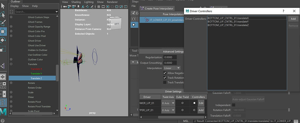
We used the joints to drive the blend shapes by adding a pose. We rotated the joints (in the rig) and pressed Add Pose. We made single-chain IK handles for the joints.

After creating 2 mouth rig controllers, we added controls to the drivers of our poses in the blend shapes.After changing the view from Default to Advanced, I introduced controllers to each driver to be able to use the controllers for deformations. I middled mouse drag "translate" attributes of each controller into their corresponding "Add Controllers" windows.
For the next exercise, I used Blend Shapes to make an eye blink.I added In-Between Target and used Erase Target tool to change the mesh for the in-between shape.
WEEK 10
Mash Networks Mo cap
This week we learned about Mash Networks in Maya and how to apply this to motion capture data. After this, we created a man walking using mocap data and added mash network to the man to obtain a procedurally generated look with cubes.
Here I created a basic mash network by adding a distribute, signal and color node.

Random Node:
I then played around with falloff and I added a torus.


For the next exercise, I used Mash for a sphere. I added a circle nurbs and for Mash, I added curve node and connected the nurbscircle to it. I then applied a random and a signal node. I Created trails node and made sure that the playblack speed is set to play every frame. Finally, I made another nurbscircle and connected it to trails->profile curve
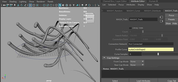
I changed the trail mode to connect by distance.
I duplicated the mash and played around with the nodes to make it look more interesting.
Fixing mash scatter noise
Step 1:
After creating a mash with the method called scatter on distribution, I connected my model(a walking man) to input mesh and I ticked the box use face area. Then, I selected all the joints on my model, changed the rotation on channel box to 0
Step 2:
Mash->Utilities->Create Mash from Points
Step 3:
Select the main joint, ''hips'' in my case, and Bind Skin. Then, select the meshfromPoints and go to Skin->Copy Skin Weights
Step 4:
Connect meshfromPoints to input under Mash Distribute. I changed the method to vertex.

Mash Network and Dynamics
I made a cube and added transform, dynamics and color node. I increased the bounce on dynamics.
I created a Mash Constrain on Distribute and a Controller Null
Plexus man
For the next exercise, I made a plexus walking man. I first made a mesh from a platonic solid. I changed the distribution type to mesh and the method to Random Face Centre. I used a signal, offset and trails node.
Finally, I added a lambert material and ramp.
Into trails, I made a curve

Crumbling Man
Additionally, I created a crumbling man. I started by creating a mash from a cube and changing the distribution method to mesh.

At a negative frame, I set the character to a T pose by selecting all the joints and adjusting their rotation to 0.
Then, MASH-> utilities ->create mesh from mash points
I selected mesh from points and the hips and then I clicked on bind skin under rigging tab.
I selected the walk_skin and the the meshfrompoints to copy the weights. MeshfromPoints becomes the input for mash distribute. Then, I created a color node.

Next, I added Dynamics. I added a channel randomiser inside dynamics and I set it up to position strength and increased the strat value. I made another one and set it to rotation strength. Then, I created falloff inside the position randomiser set it to a cube and adjusted its size and position in order to make the man break while he is walking.

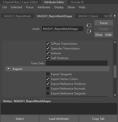
Finally, I added light and a camera. Also, I applied aiStandardSurface material to the model. In order for Arnold to render the colors, I need to go to ReproMeshShape and tick Export Vertex Colors. Then, inside standard surface, on color, I need to choose aiUserDataColor and to type into attribute section ColorSet.
The last step was to export the mash to Alembic (Cache->Alembic->Export Selection to Alembic). Then, I could hide the mash and the repromash.
Finally, I imported the .abc file into the scene
WEEK 11
Spline Ik and Influences
This week we looked at spline Ik and Influences.
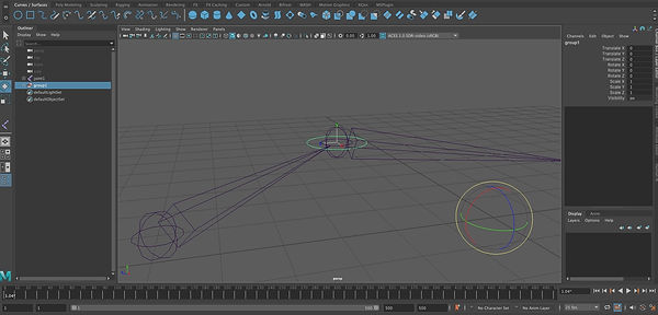
The first thing that we talked about was about joint chains that are not running in a straight line. We created a nurbscurve, parent it to the joint and zero out the transform numbers on the nurbscirlce so it snaps. Then, we unparented it and freezed the transformation, but that was actually reseting it like in the image from right:

The right way to do it:
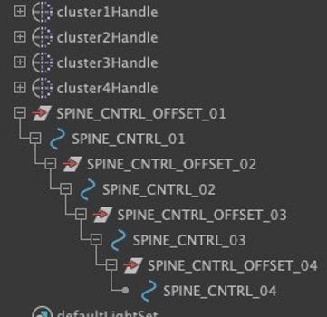
-create the nurbscircle, group it(I called the group JT_CNTRL_OFFSET)
-parent the group to the joint
-zero out the transform and rotation numbers on the group
-unparent (the controller is now snapped to the joint)
-freeze transformation on controller

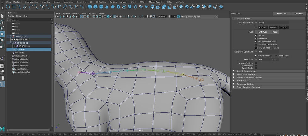
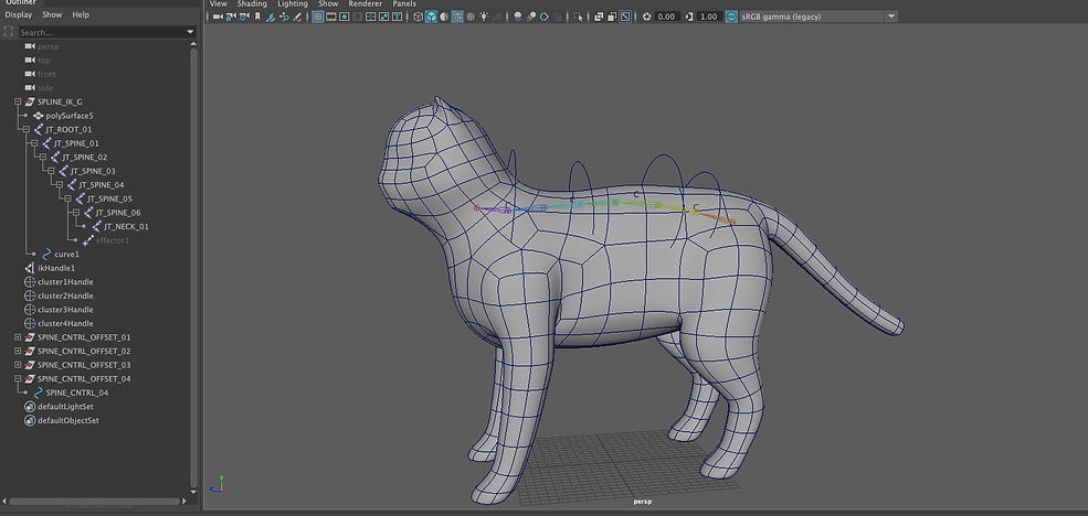
For the next exercise, we used a model of a cat and talked about what spine Ik does and how to create it:
-Skeleton->create Ik Spine
-click on the second joint from the beginning and on the second joint from the end
This will create an iKhandle and a curve that adjusts the spine.
However, in order to control the curve easier some further steps need to be made.

-In animation tab, we selected the vertex we wanted to create a controller on ->Deform>Create Cluster
Then, we created nurbscircles and we grouped them.
Snapping the controllers to the joints:
-select the group containing the nurbscircle and the joint and hit P
-zero out the offsets
-unparent again
-freeze the transformations of the nurbscircle
We made a point constraint for the controller and the cluster
We then parented everything in the correct way.
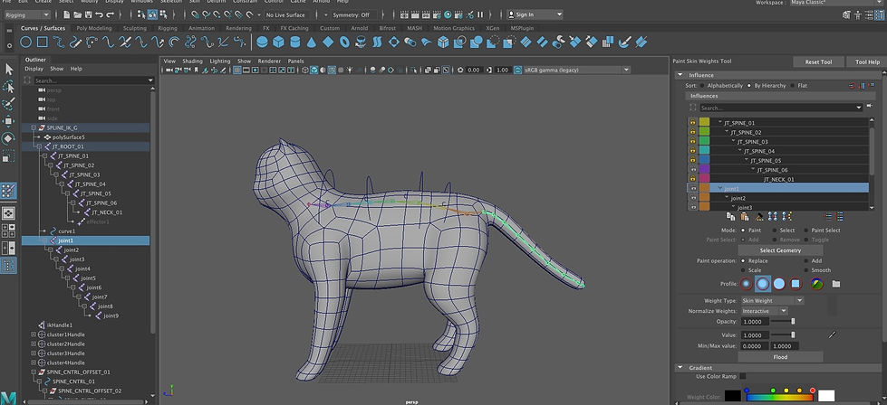
Adding extra joints to a skinned object:
-we created the joints for tail and connected them to the spine
-we selected the mesh, then edit->influences->add influences and now the new joints appear in the paint weight tool
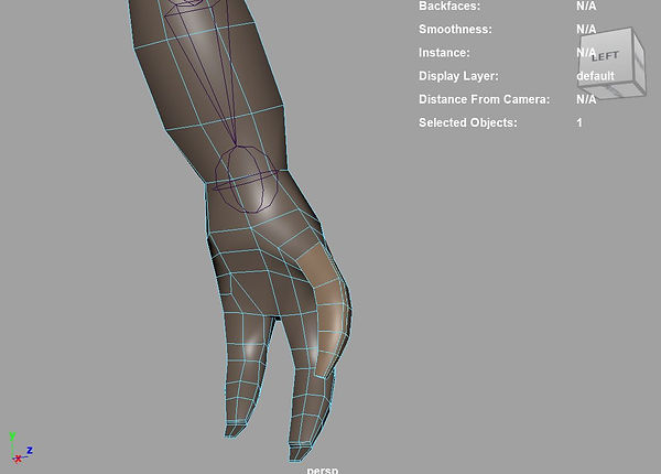
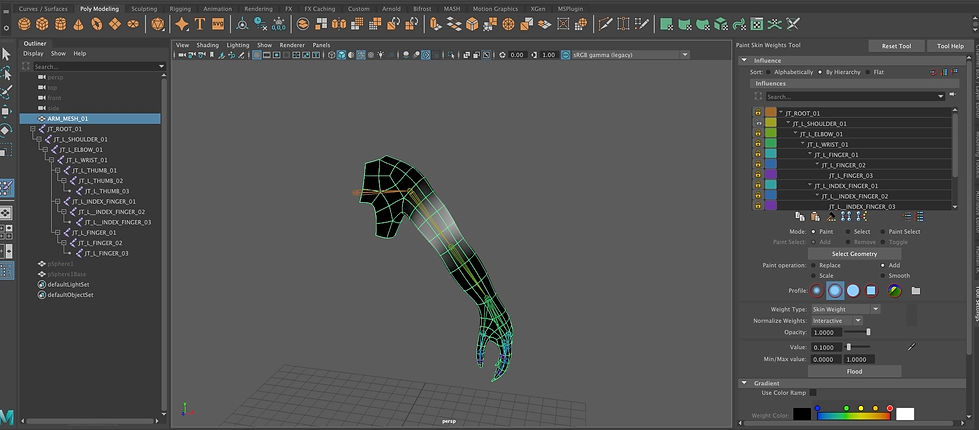
How to use meshes as influences for deforming the skin?
For this exercise, we created a sphere that will represent a muscle for our hand model and we parented it to the shoulder. We added the sphere as a influence by selecting the mesh then the sphere, and went to skin->add influence. We unlocked the shoulder and sphere into paint skin weights and then we started painting.
Note: we used the paint mode with 0.1 value. Finally, when we scale the sphere, the shoulder scales accordingly.
Then, we wanted to set a driven key so when we move the elbow joint, the muscle will get scale accordingly. Sphere is the driven and the elbow joint is the driver
WEEK 12
Fur
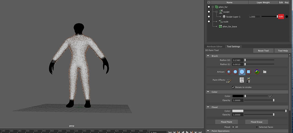
This week we learned how to apply fur. We used a model that is already rigged. The workspace used was XGen-Interactive Groom. Then, we created interactive groom splines options. The options were adjusted depending on how we wanted the fur to look.

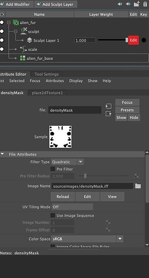
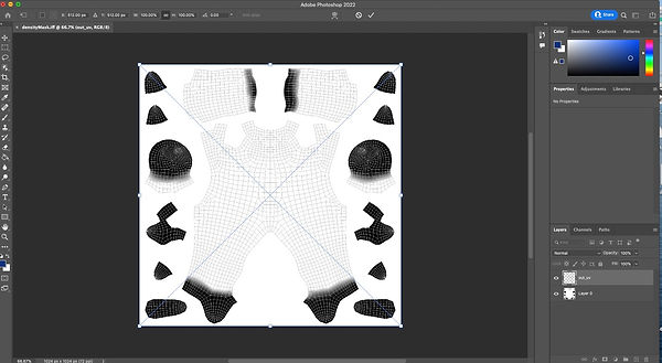
We then wanted to remove fur from certain areas such as hands, feet, head, so we went to Generator->Density Mask, then Create Map Options. We saved the map into source images folder and called it density mask. We chose a harsh brush (3rd one) with the black color and we painted what we wanted to remove. By holding shift we can obtain blur.
The next step was to bring the density mask into photoshop. However, in order to obtain the right painted areas we had to go back to Maya->UV Editor and UV Snapshot where we changed the size to 1024 because that is the size of our image and called it outUV. In photoshop, we added the new tiff over the first layer. By selecting the areas that should be just black and holding command+delete, we made the, black. When we finished with all the adjustments, we saved it as a copy and brought the image into fur base->density mask.


I started grooming by adding sculpt layers and using brushes such as comb, length, part.

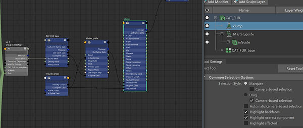
Then, I added twice the cump modifier and I played around with the density and other settings. In order to get the clump follow the direction of the fur, I made the setup below in the node editor. Finally, I added a noise modifier and I changed the magnitude.


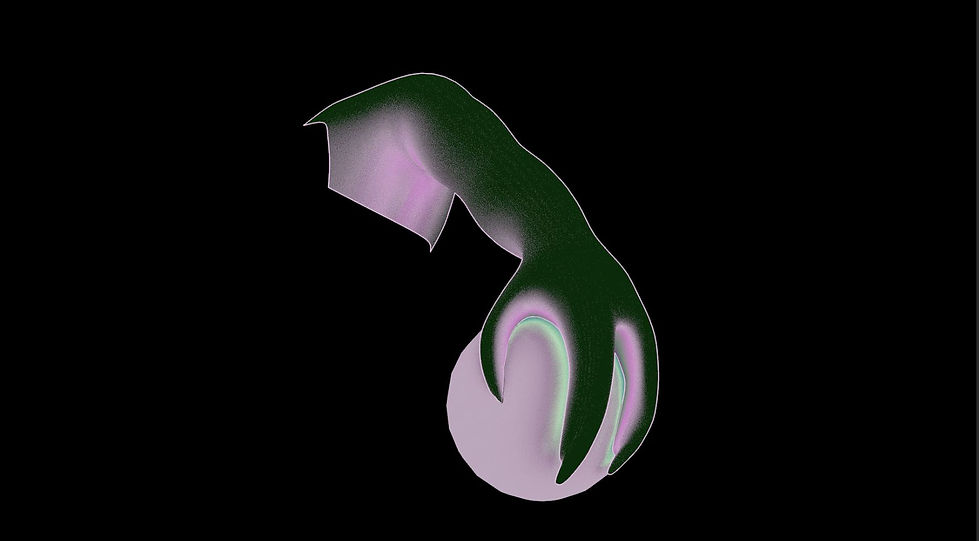
The next step was texturing the fur. I applied aiStandardHair and on base color I imported a picture with many colors and I played with melanin to make it lighter/darker.
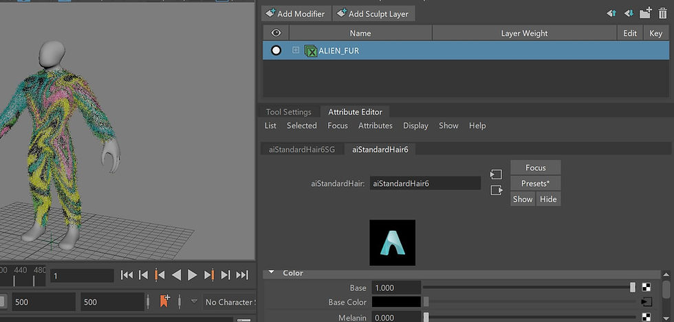
Finally, I added a Physical Sky light and I made it look like nighttime. I played around with different settings such as emmision and tint to obtain a reflective colors effect that will shine in the dark.

Final result:

WEEK 13
SUB PIVOT CONTROLS - SQUASH AND STRETCH
This week we learned how to create sub pivot controls for legs. I used a leg of a cat in order to explore this. We also had a look on squash and stretch.
I first created an ikhandle for the leg using rotate plane solver that I parented to the paw control. I made another one for the ankle by using single chain solver.
I then made the toe tap set up by making a group from ikhandle_toe and moving the pivot control to the toe joint. The next step was to create leg flex and twist set up where I used the same process, but grouping first the ankle and the foot(which made the flex) and then the flex,
The toe pivot and ankle setup was similar to the process I explained above.
Finally, I created custom attributes to control the movement of the foot, ankle and toe easier. I selected the paw control and click on add attributes in attributes tab.

In windows->general editors->connection editor, I selected which rotation controls (X/Y/Z) I wanted to be adjusted when I adjust the custom attributes in the channel box
For the next exercise, we explored the stretch of an arm.
First, I created an ikHandle for the arm and a controller(nurbsCircle) for the ikHandle. Then, I applied point constrain. I created a distance tool. Then, I had to work out the distance between the shoulder joint and ik. I wanted to make Maya when the distance number is less than 6.1 not to do anything, and to only apply scale to the joints when the number is biggerand I did that by creating an expression.

First, I added an attributed to the ikhanle called outScale

In the node editor, I brought in the ikhandle as well as the shoulder and elbow joint.I connected the outscale to the scale x of the joints

Assignment 2
For this assignment, I was required to demonstrate a range of the techniques which have been taught in the second part of the course. I modeled a cat in Zbrush, textured it in Substance Painter and then I rigged in Maya. The techniques that I demonstrated are:
-modeling for deformation
-skinning and painting weights
-subpivot controls for feet
-custom attributes
-ik handles, rotate plane solver, single chain solvers
-fur
I modeled the cat in Zbrush, then I brought it in Maya but because it contained a lot of polygons and painting the weights became difficult, I had to go back to Zbrush, and create a low poly version of my model. I added a displacement map of the high poly version to regain all the details.

Here is a recording of the initial process of modeling, as I then moved on a machine at university.
I used an image with a cat skeleton as a reference when I created the joints, and decided to add 2 more extra joints to make painting the weights easier.


Then, I created ik Handles for legs,Ik spline Handle, clusters and pole vectors for knees. I added controlls and custom attributes for feet such as toe tap, flex, twist, toe pivot, ankle movement.

I then painted the weights.
I then did the texture in substance painter.


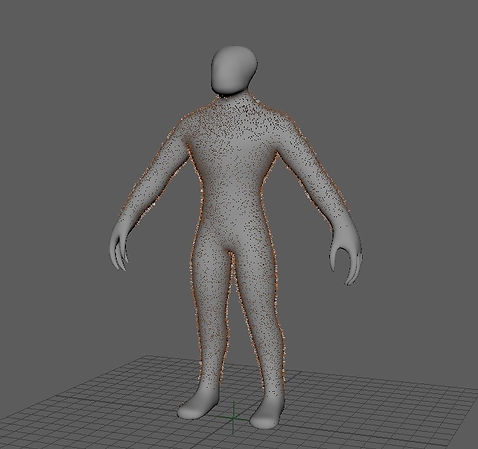
Next step was to create fur in Maya. This step was complicated for me as my laptop kept crashing a lot, so I had to move again on a machine from university. The screenshots below are from what I worked on my laptop, but the final fur I made it in uni because I could increase the density without Maya crashing. However, the process was the same.
I applied the fur and then I painted the density mask. I didn't want hair on the face and on paws so I painted it black. Then, I imported the density mask in Photoshop in order to make it more accurated and then I imported back in Maya.
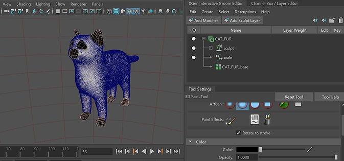


I set up the guides and started grooming. I played around with comb, length and place brush. Then, I added clumps and finally I set up the rendering.

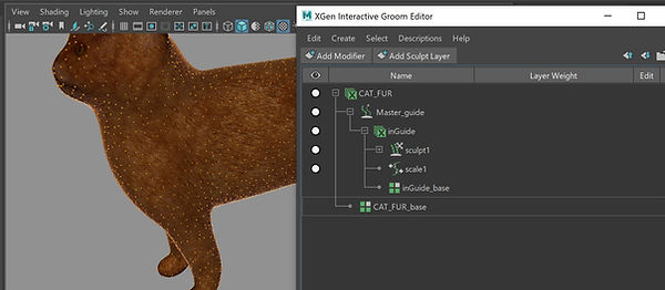


Renders with fur added:

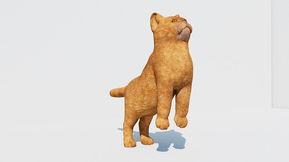
The render below does not include the fur, because my laptop was too slow to let me animate the model with the fur added.