3D MATCH MOVING
WEEK 1
Nuke 3d and camera projection
In the first week of the module, we got introduced to the 3D space within Nuke. We learnt how to make a 2D image appear as it has depth, by using camera projection.
To get in the 3D view: TAB
To navigate: CMD/SHIFT +rotate around the scene; ALT+ move around
To scale: CMD+SHIFT
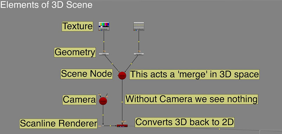
We brought in a 3d cylinder and color bars node to add a texture to it. We added a scene node, that acts as a merge (merging all 3d assets). Then, we brought in a cube and applied texture to it. We added a camera and connected the scene to it. We connected the obj/scn pipe of a ScanlineRender node to scene and cam pipe to camera. Finally, we made ananimation.

We also created a camera projection. We used a tunnel image.
Method 1:
Nodes:
-Project3D to the bg image-> puts the image onto geometry
-cylinder
-scene to the cylinder -> make it in a 3D environment
-scanlineRender -> converts 3D back to 2D; connect obj to the scene, and cam to camera
Then, we adjusted the rotation and scale of the cylinder to make it look like a tunnel. We added another render_camera and named it Project_cam and connected to the project3d. It sets a projection of the image. We created a static frame by turning off the rotation and scale animation.

Method 2:
Instead of using cam_projection node, we used a framehold that we connected to render_cam first and then to project3D

OUTCOME (SECONDS 20-23)
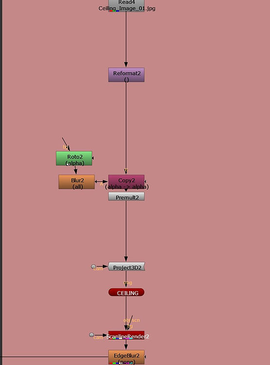
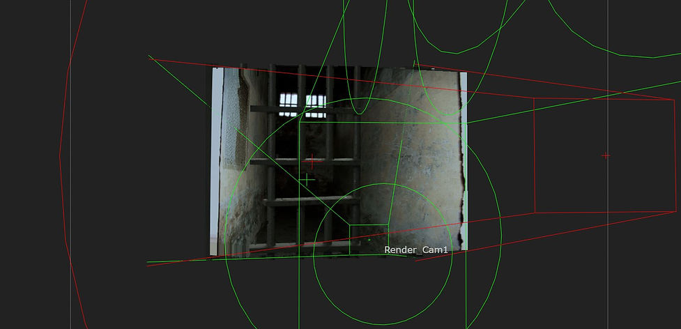
In the next exercise, we created a cell by using 2D images. First, we roto out each part: ceiling, floor, wall, bars. Then, we bring in a projected and connect cam pipe to camera projection. We can hide the new connection by selecting the dot and clickingon ''hide input''. Then, we bring in card node, so our images are projected to that cards. We projected various parts of the image to several cards, then moved them to build up the room. We add scanlineRender and connect cam pipe to camera.
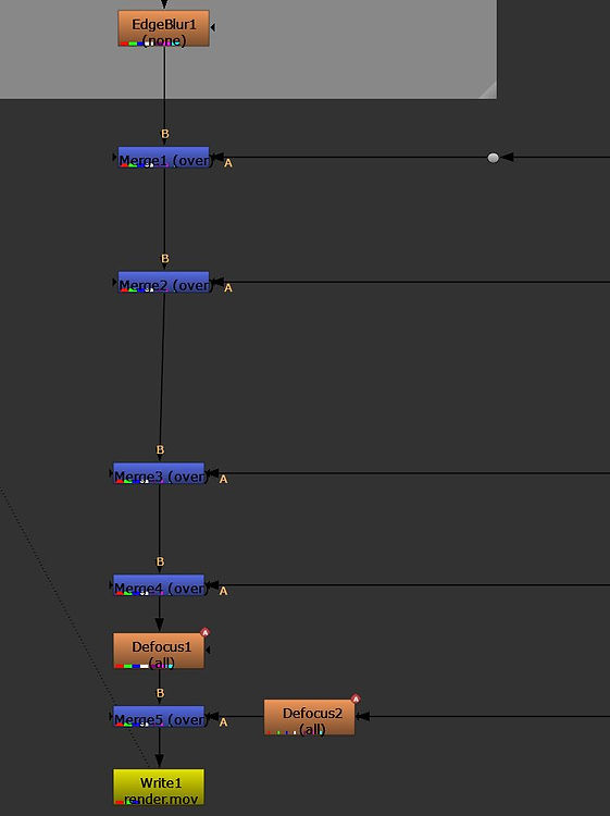
We need to set the number of samples to render per pixel, in order to produce motion blur and antialiasing.

WEEK 2
Nuke 3d Tracking
This week we studied 3D tracking. We were introduced to lens distortion and told the reason why lens distortion is relevant for 3D tracking.
As merging a 3d sequence with a live backplate will not generate a successful outcome, we need to turn the live backplate into 3d environment by using 3d matchmoving software.
Lens distortion is a deviation from the ideal projection considered in pinhole camera model. It is a form of optical aberration in which straight lines in the scene do not remain straight in an image.

For the first exercise, we tracked a scene where lens distortion is applied. First, we add a camera tracker to be able to track the scene, but first, we mask out the area not to track the water.
After we draw the roto shape, we change the mask settings at camera tracker to source alpha. Then, we can track it.
After tracking it, we click solve and autotrack-> delete unsolved, delete rejected; update solve
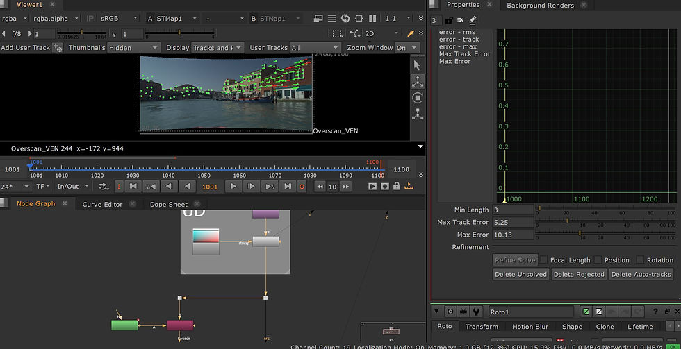

We go to Export-> Scene, Create
We add a card node, adjust its position and scale it up. We need to rotate the card to be in line with the dots.
Then, we bring in another scene node and copy paste the camera. We add the scanlinerender and connect them like in the screenshot below. Finally, we add a checkerboard node to add an image to the card.


For the next exercise, I paint out the patch using 3d pointcloud. I start by painting one of the windows after creating a framehold. Then, I do a roto shape. To apply the patch to a card, I first bring in the project3d node and connect the cam pipe to camera and the other pipe to premult. Then, between camera and project3d, I copy and paste the framehold.
I add a card node, connected to project3d (the img pipe)

As before, I activate the vertex selection and select 2 points. I click on match selection position on card tab. Then, I bring in the scanlinerender. I copy the reformat overscan node and connect it to bg pipe of scanlinerender.


STMaps
STMaps allow you to warp an image or sequence according to the pre-calculated distortion from a LensDistortion node, stored in the motion layer. The motion channels represent the absolute pixel positions of an image normalized between 0 and 1, which can then be used on another image to remove or add distortion without the warp estimation step.
For this exercise, I used the previous footage and a lens distortion grid to undistort the footage.
However, the lens was not correct for our image, that is why the outcome is not that relevant in this case.
I brought in the lensdistortion node (X on keyboard)
Lensdistortion -> Grid Analysis -> Analyze Grid to undistort the image.
->Output Type ->Displacement
Before Analyze Grid: After Analyze Grid:
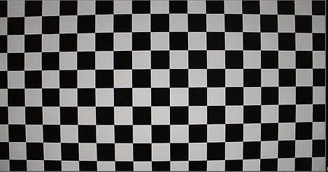
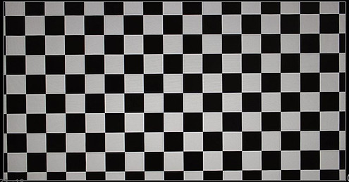
I bring in the schuffle node and view everything in motion.

Lens distortion data settings for rendering:

Then, I bring in another lens distortion node with the output mode: STMap and go to Grid Detect->Detect and Solve. Then, I repeated the same process as before


Before

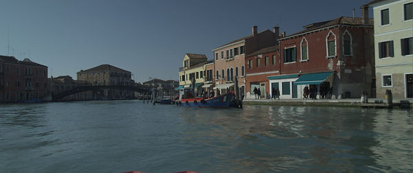
After


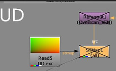
Before

After
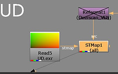

WEEK 3
3D Equalizer
This week we got introduced to a new software, 3D Equalizer, which is mainly used for tracking.
We started by getting familiar with the shortcuts and setting some new ones.


Bring in a sequence:

To make the image sequence play faster: Playback -> Export Buffer Compression File
Setting shortcuts:
-> right click on what we want to create a shortcut -> Define Shortcut -> Acquaire Shortcut -> type a shortcut->Use shortcut
Setting lenses:

Tracking:
->control +click to set the marker
->press G few times to gauge marker
->press T
->alt+click to deselect
Note: the red dot needs to stay in the same area when tracking
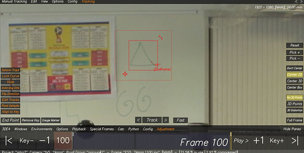
Tracking from the middle of the timeline:
->I started at frame 70 ->create the tracking marker -> R-> G->T
->frame 70 ->R (flip) -> E->G->T
Tracking objects that are leaving scene:
->when the tracking stops (object leaves scene)-> V (go back few frames) ->adjust the box to fit the unique pattern ->Q ->W (track one frame at a time) or G->T ->before it goes out of the scene E to end it

Deviation browser:
->it helps us calculate all the markers
->Config->Add Horizontal Pane->Deviation Browser
->ALT+C to calculate our points->use results
->the green line calculates an average of all our points in the scene
How to see the points?
->Deviation Browser->Show Point Deviation Curve->All Points
Note: the lower the green number is, the better the track is


Changing Lens Parameters:
->we remove everything, but not focal length
->method->brute force->adjust
->then, the green number will drop

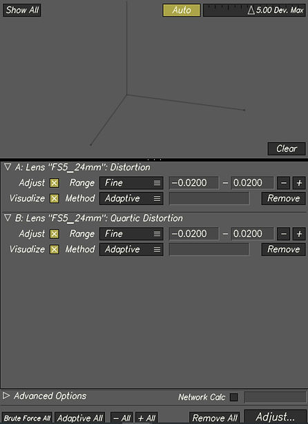
Changing Lens Distortion:
->we change the lens distortion model and select distortion and quartic distortion
->we remove everything besides distortion and quartic distortion ->clear ->adaptive all->adjust
->alt+C ->use result
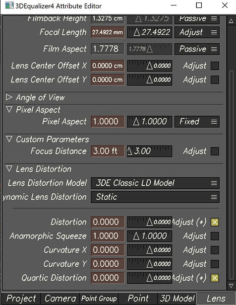
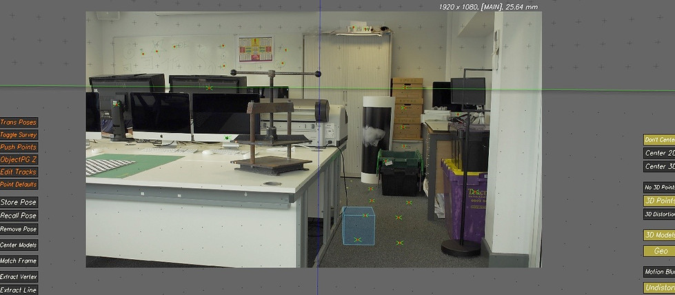
Attaching an object to a track point:
WEEK 4
Lenses and Cameras
In week 4, we had a more in-depth look at 3DEqualizer and we focused on lenses and cameras.
First, I import the footage and set the focal lenght and lens size.

Then, I start tracking from frame 78 because there the image is very sharp.
I learnt how to manually track a point in the scene when the tracking point is going off:
->use v and b to find a frame that is also sharp
->gauge and resize the box
->q to manually track
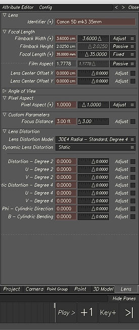
I then needed to make sure that the camera settings were all in check. Since the video was film on a Canon 5d Mk3 35mm I needed to make sure that all of these camera settings were setup in 3DEqualizer as seen above.Then, I had to track 15 points.

Setting camera constrain:

Changing parameter attributes:


Aligning the scene based on camera height:
->select the camera->change on global and set the size to 1.7 m
->select 2 points -> create constrain->162.5 m

Size is based on data survey
Aligning the scene and adding geo object on survey data:
->select 3 points that are on the floor
->3D Orientation->edit->align 3 points->XZ (to align them to the floor)
->Setting the origin point ->pick one of the points ->edit ->align 1 point ->origin

Door freemove
For the second task, I used the same process but this time was a bit more complicated as in the scene was a lot of blur. I added locators and placed a 3d object.
WEEK 5
3DE Freeflow and Nuke
This week we looked at the pipeline for working in 3DE and Nuke. We learnt how to bake a scene in 3DE and export assets into Nuke. We exported assets such as camera, locators, 3d objects.
For the first exercise, we exported a scene from 3DE including geo's and tracking points and then we put everything in Nuke.
Then, we created a patch based on the information we brought into Nuke.
Before importing the 3DE project into Nuke, I corrected the original tracking points to the real dimensions of the shot area by using the survey data. Then, I added a 3d cylinder on the floor.

Before exporting we need to bake the scene: Edit->Bake Scene.
Then, we go to export project that exports the camera and we add the file to matchmoving->camera.
We select the points and the locators and then we go to Geo->Export OBJ. We add the file to matchmoving->geo.
After that, we export the lens distortion: File->Export->Export Nuke LD_3DE Lens Distortion Node and we add the exported file into matchmoving->undistort.
Finally, we export the cylinder: 3D Models->Export Obj File and we put it to matchmoving->geo


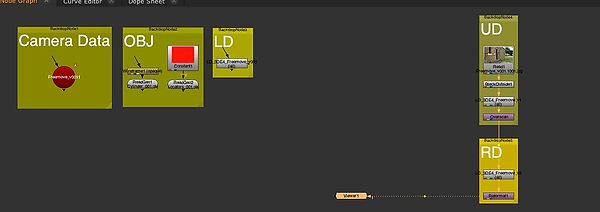
Once in Nuke, we compiled all the data into nodes in the graph editor and we organized the data into backdrop nodes. Then, we undistorted and distorted the image sequence using the data that was exported from 3DE in order to have the tracking makers in the correct place.
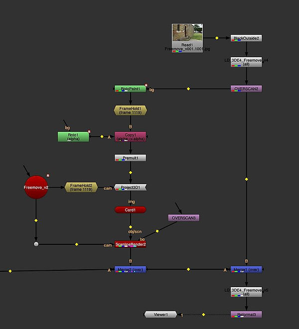
For the second task, we removed the writing that is on the white sign. We used the roto paint and frame held at 1109. We connected these to a premult and then to a card that will be placed in the 3D space along with the tracked markers on the sign. At the end, we placed the overscan node.

WEEK 6
Surveys
This week we used survey data in order to create points and with that points, making tracking points.We learned how to use all the provided survey data and measurements to track elements more precisely in the 3DE scene.
The steps I followed:
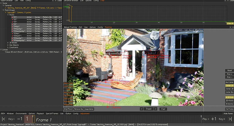
A. I first created a point that will be the origin point for the others. The point is located at the edge of the decking from the reference image. I changed the survey type to exactly surveyed.
B.Then, I added more points but placed in the correct location using the survey data.I Put the exact measurements in Position XYZ fields and went to Preferences to change the Regular Units to the unit I had my measurements in.
C.Once I made enough points, I went into manual tracking mode to complete these tracks and made sure that the tracking was in the correct location of where the points are in the 3D space.
D.Finally, I made sure that the tracks in the manual tracking space line up with the correct information in the lineup display. In order to achieve this, I readjusted the tracking point to fit within side the x cross.





Assignment 1
For the first assignment, I used 3DE to track a scene with a minimum of 40 tracked points that have a low deviation. Then, I had to align the points in the scene using the given survey data and add a 3D cube to the scene. After doing this, I needed to export assets such as camera, LD data, locator geo, and 3D cube to Nuke. All the data needed to be compiled in order to play the video and combined with 3DE data.
Finally, I had to do some clean-up for the fire exit sign in the scene.
My process:
1. Importing the video into 3DE and adjusting the settings
After importing the video, I set up the camera settings (by clicking on lens)and I added the details of the camera

2. Tracking the points
I tracked 45 points, using CNTRL and clicking on the wanted area. Then I pressed G to gauge it and T to track it. Sometimes, I had to readjust the tracking box when the track stopped, and sometimes I did the tracking backward or from the middle.
I made sure that I tracked points that were close and far away from the camera. Then, I pressed "Alt C" to solve the points into 3D space. I positioned the points in places where I can use the survey data to adjust the tracks in 3D space.
3. Getting a low deviation
To get a solid track, I used the lineup view to make sure that the points were in the centre of the green crosses.
Then, I added the focal length adjustments (i changed it from ''fixed'' to ''adjust'' and I used adaptive in parameter adjustment window to get a lower deviation. Next, in lens distortion, I clicked the adjust box for distortion and quartic distortion and I used again the adaptive method.

4. Aligning the scene in 3DE using survey data
I created a distance constrain along the white cupboard using the provided data of 140 cm. This is an important step to have the points correctly scaled in the 3D space.
Next, I selected three points on the ground and then clicked "Edit/Align 3 Points To/ XZ Plane". I selected one point on the ground and clicked "Edit/Move 1 Point To/Origin".

5. Adding locators and 3D Cube to test the stability of solve
I created a cube and then I selected one of the points and clicked "3D Models/Snap To Point". I also added locators: "Geo/Create/Locators".
6. Exporting camera, LD data, locator geo, 3d cube to Nuke and undistort lens + reformat. Overlay locators and 3d cube
I baked the scene and then I imported all of the data that was needed from 3DE. I put them into backdrop nodes.
Setting up the lens distortion of the video:
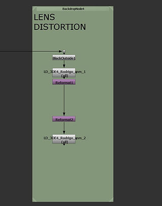
I used BlackOutside to add a border to the image sequence because the LD data added after is cutting the edges of the image. The reformat nodes allow the conversion of the footage to undistorted and distorted.
Then, I added a Scene node and connected it to a ScanlineRender node. I connected the camera to the ScanlineRender. I connected the cube and the locators to the scene. I then merged the scan line render with the original footage.

7. Place Cleanup Patch on the fire exit.
I added a FrameHold node and set it to frame 1001.
I added a RotoPaint node before it and paint out the sign.
I made a roto shape around the sign and used a blur node to feather the edges. After a premult node, I added a Scene node and connected that to a ScanlineRender node. The camera is conected to the ScanlineRender and the locators to the scene.
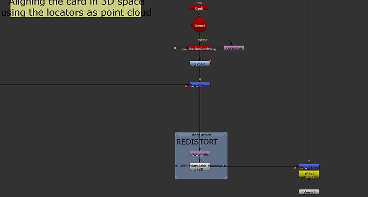
Then, I added a card and connected it to the scene node and adjusted with the locators in the 3D view.
I connected a Project3D node to the premult and then connected that to the card. I copied the FrameHold and connected it to the Cam pipe of the Project 3D node.Framehold is connected to camera.
Next, I added a grade node between the ScanlineRender node and the merge node and animated it to match the colours.



WEEK 7
Creating Shot Footage for Assignment 2
This week, I worked on creating some footage for the next assignment in which we are required to track our own scene in 3DE, solve it, align it and make it more interesting in Nuke. For my shot, I decided not to use the green screen, but the part of the studio that includes the cameras and TVs. I made sure that I applied markers to the wall and the floor so that when I come to track these shots in 3DE, they can be tracked easier. I have also did some measurements in order to create distance constrains in 3DE, for example, I measured the PC screen dimension which was 21cm (horizontal) and 11cm(vertical).
Another important step was to make a note on what camera I used, which was a Sony Fs5, and the lenses(14 mm)
WEEK 8
Surveys Continued
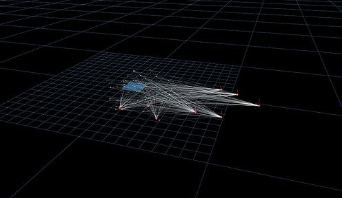
In week 8, we again had a look at survey data within 3DE. We learned how to import multiple reference images into the software where I then tracked 40 points across the reference images.
First, I brought in 9 reference images and I added a new lens for which I edited the settings. I then went through each of them to track specific points that exist acroos all of them.
After I finished with tracking the points that span across all the reference images, the next step was to compile all the reference images into an image sequence that contains the tracks.

WEEK 9
Lens Distortion and Grids
This week for the module, we again had a look at lens distortion in 3DE but this time we learned how to make use of a grid to help with the lens distortion of an image sequence. In class today I have imported a nodal image sequence and tracked points for which I used a grid to generate the lens distortion, below are my processes for this week.

With the image sequence above I tracked 20 points using reference images. In order to obtain the lens distortion I first created a new camera that contains the checkerboard. Then I used the distortion grid view where I snapped the points to the checkerboard that I have imported and I expanded the points to cover the whole grid. By doing this, 3DE can now use the checkerboard data in 3D space.
Finally, I calculated the lens distortion based on the grid I brought in.

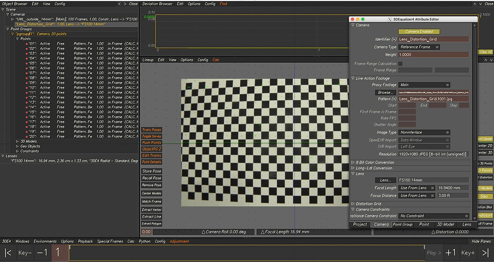

I used the menu below to calculate the lens distortion using the parameters seen above.

Final distort and undistorted images:
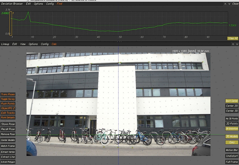

WEEK 10
Workflow Nuke to Maya roundtrip
This week we learned the workflow of taking a tracked image sequence from 3DE and combining it with a 3D object from Maya. Moreover, we used Nuke to add the lens distortion data into the exported image sequence.
The workflow that I went through:
I started in 3DE by setting up the image sequence and the camera properties. I then went to the 'export to Maya' area under the export tab and I made sure the start frame was set to 1001.
Then, I brought it into Nuke where I needed to undistort the sequence since there is no lens distortion in Maya.
After this, I opened Maya and I set the project as well as the properties of the script with the tracking points from 3DE that is needed to import. I moved the .mel script exported from3DE to scripts (in Maya setup folder) and the image sequence into source images.
Note:The scale and size of the image sequence needs to be properly set up in the placement section and also the focal length of the Maya camera.


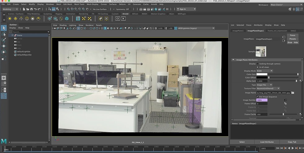
.jpeg)
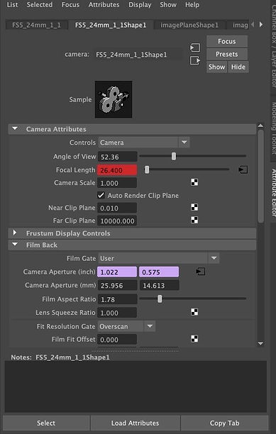
Because the world origin of the scene was already set to a tracked marker all, I didn't have to do anything special for adding new objects into the scene. I have also made sure to set up the shading of these objects and added an area light for rendering.

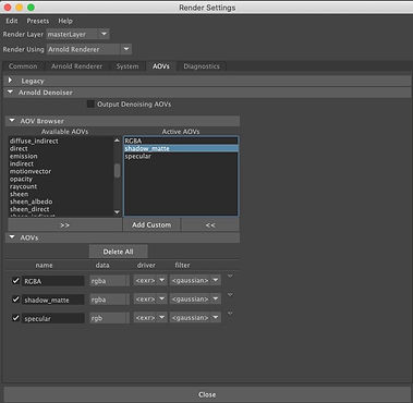

I added a poly sphere to the scene.
Finally, once I had finished rendering the shots from Maya I then brought this back into Nuke where I applied a lens distortion and merged the rendered AOVs to the original sequence to create the final shot. I have also adjusted the colors of the sphere and removed some of the yellow markers.

WEEK 11 & 12 & 13
Working for the second assignment
These weeks we focused on preparing and working on the second assignment, constantly receiving feedback from Josh Parks.
Below is what I worked on these weeks and what I learned from the feedback I got. My initial plan was to remove the PC from left side of the image, but it was really complicated because the surface where the PC was placed was not flat, so instead I removed the TV.
My first step is to do what a roto prep artist will do, to work on the background, clean up the scene, remove the markers and other objects

After I managed to remove the TV, I had a problem with the camera that was covering it when moving. The advice that I got from Josh that solved the problem, was to 2d track the camera first and then roto it on one frame, get the 2d track make most of the work, specifically move it and stick the roto to the object

Finally, I cleaned up the scene and added my objects: camera and projector. Another thing that I had to solve was the black levels. As it can be seen in the image above, the black on the projector feels a bit darker than the cameras in the back. In order to sort this out, I was advised to add a saturation node at the bottom of my nuke script and to increase the saturation so I can see better the colors. Then I can add a grade node on the projector, hold down CNTRL on gain to get the color wheel and adjust the colors in order to match the colors. Below is an example on how increasing the saturation helps us to see the colors better.


Assignment 2
For this assignment, I recorded my own scene that I tracked and aligned in 3DE. I solved the scene and composited in a 3D asset to demonstrate stability of solution. I modeled a camera that I imported into the scene, and I downloaded a projector and a speaker.
Original Footage
After importing the video, I set up the camera settings (by clicking on lens)and I added the details of the camera. I tracked 45 points, using CNTRL and clicking on the wanted area. Then I pressed G to gauge it and T to track it.I made sure that I tracked points that were close and far away from the camera. Then, I pressed "Alt C" to solve the points into 3D space. I positioned the points in places where I can use the survey data to adjust the tracks in 3D space.


To get a solid track, I used the lineup view to make sure that the points were in the centre of the green crosses.
Then, I added the focal length adjustments (i changed it from ''fixed'' to ''adjust'' and I used adaptive in parameter adjustment window to get a lower deviation. Next, in lens distortion, I clicked the adjust box for distortion and quartic distortion and I used again the adaptive method.
I created a distance constrain along the TV screen (11 cm) using the measurements I made in the studio. This is an important step to have the points correctly scaled in the 3D space.
Next, I selected three points on the ground and then clicked "Edit/Align 3 Points To/ XZ Plane". I selected one point on the ground and clicked "Edit/Move 1 Point To/Origin".
I created a cube and then I selected one of the points and clicked "3D Models/Snap To Point". I also added locators: "Geo/Create/Locators".
Then, I baked the scene and then I imported all of the data that was needed from 3DE. I put them into backdrop nodes.
Setting up the lens distortion of the video:
I used BlackOutside to add a border to the image sequence because the LD data added after is cutting the edges of the image. The reformat nodes allow the conversion of the footage to undistorted and distorted.

After compiling data into Nuke, I set up the lens distortion and I removed the TV(from right side) by applying a card.I used BlackOutside to add a border to the image sequence because the LD data added after is cutting the edges of the image. The reformat nodes allow the conversion of the footage to undistorted and distorted.
Removing the TV:
I added a FrameHold node and set it to frame 1001.
I added a RotoPaint node before it and paint out the TV.
I made a roto shape around it and used a blur node to feather the edges. After a premult node, I added a Scene node and connected that to a ScanlineRender node. The camera is conected to the ScanlineRender and the locators to the scene.
Then, I added a card and connected it to the scene node and adjusted with the locators in the 3D view.
I connected a Project3D node to the premult and then connected that to the card. I copied the FrameHold and connected it to the Cam pipe of the Project 3D node.Framehold is connected to camera.
Next, I added a grade node between the ScanlineRender node and the merge node and animated it to match the colours.


Then, I cleaned up the markers.


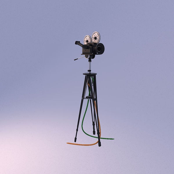
Then, I added a speaker by downloading green screen footage and tracking it, I modeled a camera in Maya that I added into the scene and a projector that I downloaded as a fbx. In order to match the colors with the scene, I added a saturation node that I increased it up to size 8 to see the colors better, which I finally disabled at the end.


Tracked scene:
Initial Plan:


Breakdown:
Final Composition: